Master Thesis by Tesfaye Asmera Mengesha
Thesis Title:
3D Reconstruction and CAD Model Generation for Augmented Reality Based Intuitive Robot Path Teaching
Singapore Institute of Manufacturing technology (SIMTech)
Mechatronics Research Group(MCH)
The main objective of this thesis is three dimensional reconstruction and generation of computer aided design (CAD) data from multiple images for vision based robotic application. Data acquisition system consists of camera mounted on a robot end-effector. The images are collected by moving the robot around the work piece. During the acquisition the pose of the robot is recorded to find relative pose of a camera for processing phase. After the acquisition the images are loaded into interactive graphical user interface (GUI). Using human in the loop (HIL) approach the operator selects few corresponding features by mouse clicking. This solves the correspondence problem and segments the geometry we are looking for on the whole image plane. In addition, this method increases the processing speed as only few points are used during reconstruction step. Based on the collected corresponding points the 3D information is reconstructed using triangulation algorithm. The reconstructed 3D points give geometric property of work piece. Using this information the generated point clouds are transformed to local frame for further interpolation. The populated cloud is transformed back to the robot base frame for generation of standard STereoLithography(STL) file format. The transformation to robot base frame is needed to avoid localization during task -planning. The proposed method increases human robot interaction (HRI) by using interactive 3D reconstruction approach. In addition the result shows that the method can replace the expensive 3D shape reconstruction based on laser vision scanner in industrial robotics application.
To achieve the desired goal the implementation starts with Camera-Robot calibration. This step computes the transformation matrix between robot tool coordinate frame and camera coordinate frame.

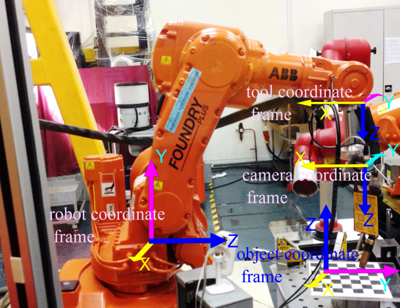
Figure System setup with associated coordinates: robot base coordinate frame, tool coordinate frame, camera coordinate frame and object coordinate system.
The computation of 3d information is necessary step to avoid localization as all coordinate information of work piece in object coordinate is known with respect to robot frame. So based on this information the robot can be commanded without any localization steps.
In this configuration Laser range finder is used to give the information where the work piece is with respect to robot base frame.
The reconstructed 3D information and the generated 3D CAD model is given in camera coordinate frame, and then transformed to robot base frame to avoid localization.

Figure name Four coordinate system for generation of 3D CAD model
The transformation matrix between object coordinate frame and robot coordinate frame is estimated using singular value decomposition.

Figure Transformation between point cloud in robot base frame and object coordinate frame.
The next step after Robot-camera calibration is image segmentation and feature extraction of image captured by the camera mounted on Robot end effector. The approach uses human in the loop (HIL) and contour detection based on the type of primitive geometry. The segmentation of image simplifies the representation of the image whereas the feature extraction step reduces the set of input data into reduced set of features.

Figure Input image

Figure Image segmentation
The feature matching uses the segments and corners to match the interest points. Given feature points in one image it computes the corresponding feature points in the other image

Figure Feature matching
In case of circular and cylindrical geometry the feature matching involves ellipse fitting. The segmented contours are fitted to ellipse equation. Based on the fitting algorithm the center, minor and major axes are computed. Here the rotation invariant assumption is hold among the two corresponding point. The corresponding points are the end point minor, major axes and the center of the ellipse.

Figure Ellipse fitting

Figure Corresponding feature points on the two views assuming the ellipse is rotation invariant
Before application of reconstruction algorithm the relative pose of the camera is computed based on the forward kinematic model of the robot and robot-camera calibration. Forward kinematic model gives the relative pose of robot end-effector. The computation of the transformation matrix between the consecutive poses depends of transformation matrix between camera and robot end-effector. The computation of this matrix depends on the robot-camera calibration phase.
Applying the triangulation algorithm different to the extracted feature points using computed camera position the three dimensional information of workpiece in front of the robot is estimated.
For different geometric primitives different algorithm is applied for three dimensional (3D) model generation. The 3D model of planar and rectangular geometry involves Human in the loop (HIL) approach for feature extraction. The plane geometry needs three points to define the plane and its surface normal.

The flow chart of 3d reconstruction algorithm for planar and rectangular geometry
From the above flow chart all the steps before the projection matrix computation is conducted by the operator. The rest of function is executed during the processing stage.

Figure Feature points selected by operator using mouse clicking

Figure Plane top surface after reconstruction

Figure Interpolation at local frame with 1mm of resolution
Given the surface normal of top surface of the rectangle and the height the CAD model of the object can be generated.

Figure Corner points on the first image and the corresponding corner points on second image

Figure Wireframe of the polygon and CAD model(in standard STereoLithography file format
Considering the circular and cylindrical objects, cylindrical object is the number of slice of circular geometry.

The flow chart and over all steps for 3d circular and cylindrical reconstruction, operator input in loop and processing stages
In the same manner of the reconstruction of planar and rectangular geometry in 3D digitization of circular and cylindrical geometry the operator loads the robot position and the corresponding images captured by camera mounted robot. Full reconstruction of cylindrical objects involves the first image to be in the full view of the camera. This helps the operator to select few points which used later for the estimation of the corresponding 3D information.

Figure n (a) First image at first pose of the robot with few bottom image coordinates selected for further processing (b) second image of cylinder at second pose of robot.
In the processing phase contour detection takes place for searching elliptic geometry on the image plane and for fitting the contour to the ellipsoid part. the following result shows the overlay of fitted ellipse on the grayscale image.

Figure (a) Contour of detected geometry (b) ellipse overlay on the original image to check whether the detected contour exactly fit to the original shape
After ellipse fitting the triangulation algorithm computes the center point and the radius of circular part of the cylinder in full view of camera, i.e. the top part of the two cylinders and the bottom part of the first cylinder should be in full view of camera mounted robot. The following result demonstrates the circular part of the cylinder in 3D plane. The result shows the information of circles in local frame for further interpolation.

Figure The reconstructed circular upper and bottom part of the cylinder for further interpolation.

Figure Interpolated point clouds of bottom and upper circular part of cylinder in local and robot frame
The main advantage of interpolation is for the population of the clouds to generate desired level of information and to achieve certain level of accuracy. In this context the circle is interpolated with 10 and with 1mm of accuracy along the height of the cylinder.
The following figure shows the polygonal meshing representation of the geometry after interpolation and 3D CAD model in standard representation.

Figure Polygonal meshing on of cylinder (on the left) and CAD model representation (on the right)
The case study of this thesis augmented reality based robot path planning and teaching for welding application. The augmented reality based path planning and teaching overcomes these problems by immersing the operator in virtual world. This technology keeps the operator in touch with real world by using the camera mounted on the robot. In addition the operator interacts with virtual objects generated
during reconstruction phase. By overlaying virtual 3D model on the captured image the operator
teaches the robot. In this particular application the operator overlay the CAD generated during
3D modeling on the on live image in the camera view. Based on the mapping information between
the virtual model and real image the operator commands the robot to execute welding application.
The following figure shows the augmentation of real work piece by virtual 3d model generated
during the processing phase. The result is demonstrated by putting the result of this thesis in the main project of this research project.

Figure This figure shows the overlay of 3d model on the image captured by camera mounted robot.

Figure Interactive path planning and teaching using augmentation
Findings and Achievements:
Standard CAD model of work piece from camera image.
Robot localization based on 3D reconstruction algorithm.
Potential Impacts:
As a module of CAD model generation in industrial robots.
Industry Applications:
Path planning and teaching, Welding, Deburring and machining robots.