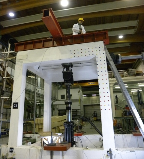
MEMSCON project aim is to test a new-generation monitoring system based on MEMS and wireless transmission. This is an integrated system consisting of a set of small acceleration and strain sensors, distributed within a concrete structure. This unit automatically records and interprets the data, and provides the user with a damage index representing the structural safety after a seismic event. To test these sensors a concrete structure, Figure 1, was stressed with a shock wave that replicate a real earthquake.
 |
| Figure 1: Concrete structure on which MEMSCON is tested |
To assess the reliability of these algorithms the output of the MEMS monitoring system were compared with those coming from other measuring systems, such as linear voltage displacement transducers (LVDT) and multi-stereo camera system, GaMoCap.
GaMoCap system was used to map the displacements of marker placed at the base of one pillar, Figure 2-left, and at the intersection of the pillar with the upper part of the concrete structure, Figure 2-left.
|
|
|
| Figure 2-left: Base of the pillar with markers | Figure 2-right: Head of the pillar with markers |

In Figure 3 is reported a draft of the GaMoCap configuration that display the disposition of the 4 cameras, the connection with the pc and the trigger device.
 |
| Figure 3: Disposition of cameras, pc and trigger device of GAMOCAP system |
Images captured were saved directly on the RAM of a PC and at the end of the test transferred on an hard disk. The camera setup used provided images with a resolution of 1600×1200 pixel at 10 Hz. Trigger is given by an external source to assure synchronisation between the 4 images.
In Figure 4 is reported 3D points and the mesh reconstructed for the base of the pillar and the marker at the head.
 |
| Figure 4: 3D points meshed and trajectory of points at the top of the grid of the base and head of the pillar |
Below there is video of the 3D meshed-points reconstructed during one trial with a maximum displacement at the top equal to 34 mm and the trajectory in Y direction of the point at the head of the structure.
Displacement results measured with vision system GaMoCap were compared and validate also by the actuator displacement measurement system, Figure 5.
 |
| Figure 5: Comparison of displacements measured by Gamocap and the hydraulic actuator |
The measurement campaigns were conducted in the framework of the MEMSCON project headed as Task Manager and Dissemination Manager by Assistant Professor Ing. Zonta Daniele, with the help of Ph.D students Trapani Davide.